
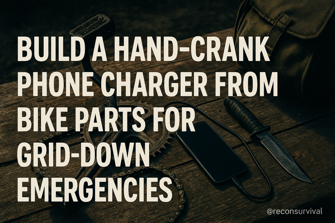
Thirty-six hours into a blackout, you still have bars but your phone is bleeding down—17%, 16%—and the weather net is lighting up with warnings you can’t afford to miss. The gas station’s dark. The generator across the street just sputtered out. You look at the dusty bike hanging in the garage and think: there’s energy in that wheel. I’ve been in that moment—on storm deployments and in field trainings—and I’ve built hand-cranked chargers from scavenged bike parts that kept comms alive when the grid didn’t. It’s not a gimmick. Done right, you can turn human effort into a dependable 5V lifeline for phones, radios, power banks, and GPS units.
This guide walks you, step by step, through building a rugged, efficient hand-crank phone charger from common bicycle components. We’ll cover which parts work best (hub dynamos vs. DC motors from old treadmills and e-scooters), how to gear for usable voltage at comfortable cadence, and the electronics that make it safe for your devices—bridge rectifiers, smoothing capacitors, and buck converters that lock in a clean USB output. You’ll get a clear parts list, wiring diagrams you can sketch on a scrap of cardboard, mounting options (from clamp-on stands to 2×4 field rigs), and realistic performance numbers so you know exactly how long you’ll crank to top up a phone.
We’ll also troubleshoot the common failure points—slipping belts, spiky voltage, overheated regulators—and talk upgrades like supercapacitor buffers and power-bank staging for small-group use. Underneath the hardware is a simple truth: preparedness is stewardship. A small, homemade charger won’t just serve you; it can help you check on an elderly neighbor, send a status text to family, or power a shared comms node. If you’re ready to turn pedals into peace of mind, let’s build something that matters.
What a Hand-Crank Can—and Can’t—Do: Power Basics and Realistic Expectations for Phone Charging
What a Hand-Crank Can—and Can’t—Do: Power Basics and Realistic Expectations for Phone Charging
Picture a stormy week with the grid down and cell towers limping along. You don’t need Netflix; you need texts to go through, maps to load, and a weather update. A hand-crank charger made from bike parts can absolutely keep a phone alive for that work—but only if you understand the limits and design for them. This is patient, deliberate power, the kind of stewardship that favors essentials over excess.
A Realistic Power Budget
Human arms are not bicycle legs. While a trained cyclist can push 100–200 watts on pedals, hand-cranking sustainably delivers about 5–10 watts for several minutes at a time. Many bike dynamos (hub or bottle) are rated 6V AC at 3W around 10–15 mph. With efficient rectification and regulation, you can expect 2–6 watts of usable USB power from a hand setup.
Modern phones store roughly 11–18 watt-hours (Wh) of energy (3,000–5,000 mAh at 3.7V). Accounting for conversion losses (20–40%), bringing a dead phone to full may cost 14–25 Wh. At 5 watts output, that’s 3–5 hours of cranking. Practically, plan for top-ups: 15 minutes of steady cranking at 5W yields ~1.25 Wh—often enough for dozens of texts and a quick map check.
Quick math you’ll use:
– Watts = Volts × Amps. USB at 5V × 1A = 5W.
– Time (hours) ≈ Energy needed (Wh) ÷ Power output (W).
Voltage and Stability Matter
Phones expect clean, steady 5V on USB. If voltage sags or spikes, they’ll connect/disconnect or refuse to charge. A dynamo’s AC must be rectified and regulated. The most resilient setup uses a rectifier to DC, a smoothing capacitor, and a quality 5V buck/boost regulator—or charges a small buffer (power bank or supercapacitor) first, then the phone. Don’t aim for fast charging protocols (9–12V PD); target a rock-solid 5V at 1A.
Common Pitfalls and Fixes
- Unstable output: Add a buffer (power bank) between crank and phone.
- Overvoltage at high RPM: Use a regulator with overvoltage protection or a TVS diode clamp.
- Disappointing charge rate: Your real output is likely 3–6W. Track expectations, not marketing numbers.
- Fatigue: Use intervals (5 on/2 off). This is a marathon, not a sprint.
Key takeaway: A hand-crank rig is a communications lifeline, not a wall outlet. Design for 5V, 1A steady, plan for incremental top-ups, and you’ll steward your effort into reliable, mission-critical phone use. Next, we’ll map the parts—what to salvage from a bike and how to make the electrical side behave.
Scrounge List and Tool Kit: Bike Parts and Simple Electronics You Actually Need
Scrounge List and Tool Kit: Bike Parts and Simple Electronics You Actually Need
Picture this: the grid’s down, you’ve got legs that still work, and a neighbor’s shed full of retired bikes. Good stewardship isn’t just about what we store—it’s about what we can repurpose with skill. Here’s the lean, proven list you actually need to turn pedal power into a phone-safe 5V supply.
Bike Bits to Harvest
- Rear wheel with tire: 26–29 in. wheels give a smooth “flywheel” feel. Keep the tire; it provides friction drive.
- Frame/stand option: A basic repair stand or a DIY stand (2x4s) that lifts the rear wheel. Goal: stable, no wobble.
- Cranks and chain intact: You’ll want normal pedaling cadence (60–80 RPM). No special gearing required at this stage.
- Bottle or hub dynamo (optional): A 6V/3W hub dynamo is reliable; a bottle dynamo works but may slip in wet conditions.
Why: The spinning rear tire is a consistent surface to drive a generator by friction. Stability equals safer, longer sessions.
Generator Options (Pick One)
- 12–24V permanent magnet DC motor (best): Small scooter or treadmill motors (150–350W rated) make excellent generators. Target shaft speed 1,500–3,000 RPM at an easy pedal cadence via tire friction.
- High-quality hub dynamo: If you have one, it’s predictable (6V AC at ~3W), but you’ll need rectification and careful power management.
Why: A PMDC motor outputs DC proportional to speed—simple, durable, and abundant in scrap piles.
Electronics That Make It Phone-Safe
- Bridge rectifier (if using AC dynamo): 4–6A, 50V rated, or four 3A Schottky diodes.
- Smoothing capacitor: 2,200–4,700 µF, 25V to tame ripple.
- DC-DC buck converter with USB: 6–24V input, 3A output at 5V. Prefer models with current limiting and heat sink. Avoid boost-only modules.
- Inline fuse: 2A–5A fast-blow on the input side.
- Wiring: 16–18 AWG stranded, silicone-insulated if possible; USB breakout or a quality USB-A/C socket.
- Optional: Inline volt/amp meter, SPST switch rated 5A/24V, alligator clips for temporary setups.
Why: Your legs are a variable source. The buck converter stabilizes 5V so your phone survives voltage spikes.
Hand Tools and Mounting Hardware
- Hex keys (4–6 mm), adjustable wrench, Phillips driver, chain tool.
- Hose clamps, zip ties, angle brackets, scrap plywood/metal for a motor mount.
- Multimeter and a test load (10Ω, 10W resistor) to verify under load.
Common Mistakes and Quick Fixes
- Overvoltage into the buck: Add the fuse and test with the 10Ω resistor before plugging in a phone.
- Slipping drive: Use a rubber roller or wrap the motor pulley with bicycle inner tube; increase spring tension.
- Undersized wires = heat: Step up to 16 AWG.
- Noisy output: Increase smoothing capacitance and ensure solid ground connections.
Key takeaway: Keep it simple, safe, and serviceable. Next, we’ll map drivetrain ratios and mounting, turning this parts pile into reliable pedal power.
Crank, Chain, and Ratios: Turning a Bike Frame into a Smooth Hand-Drive Generator
Crank, Chain, and Ratios: Turning a Bike Frame into a Smooth Hand-Drive Generator
The lights are out, neighbors are checking on each other, and you’ve got a stripped bike frame on a stand. This is where a calm hand and good ratios turn human effort into usable power. Getting the crank, chain, and gearing right is what makes the difference between a punishing grind and a smooth, sustainable hand-drive you can run for 10–20 minutes at a time—long enough to top off a phone and call family. Think of it as good stewardship of your strength and your scavenged parts.
Choose a Ratio Your Hands Can Hold
Your phone ultimately needs 5V; your generator (a small PMDC motor) typically needs 1,000–2,000 RPM to make a stable 9–16V that a regulator can tame. Most folks can hand-crank a bike’s crankset at 60–90 RPM. Aim for a total ratio of about 15:1–25:1 so your motor spins in the right zone without feeling like a meat grinder.
Practical example:
– Front chainring: 42T
– Rear cog: 14T (3:1 speed-up)
– Friction roller on the rear wheel to motor: use the wheel as a big “pulley.” A 26″ wheel has ~330 mm radius. A 60 mm rubber roller on the motor shaft gives ~330/30 ≈ 11:1 speed-up (radius ratio).
– Total: 3 × 11 ≈ 33:1. At 60 RPM on the crank, motor ≈ 1,980 RPM—right where you want it under load.
Too high a ratio and you’ll stall and fatigue; too low and you won’t reach charging voltage. Start with a 50–60 mm roller; swap to 40–45 mm only if you’re short on voltage.
Mounting the Drive Cleanly
- Frame: Clamp the bike in a repair stand or between sawhorses. The bottom bracket becomes your hand-crank; pedals make good handles.
- Chainline: Shift to the smallest rear cog to maximize speed. Keep the derailleur for tension.
- Motor mount: Press the motor’s rubber roller against the tire or bare rim using a hinged bracket, U-bolts, and a bungee for preload. Tire contact is quieter; bare rim reduces slip in wet conditions. Clean contact surfaces with alcohol.
- Freewheel matters: Using the rear freewheel lets you pause without back-driving the crank. It also smooths feedback.
Smooth, Sustainable Feel
- Add flywheel: Leave the rear wheel on. Its inertia evens out pulses so your hands don’t fight the motor every half turn.
- Lubricate: A clean, lubed chain reduces wasted effort.
- Guard against slip: If the roller chatters, increase preload slightly or roughen the roller with 80–120 grit sandpaper.
Common mistakes:
– Over-gearing: Feels “sticky,” voltage sags under load. Go to a larger roller or a bigger rear cog.
– Under-gearing: Spins easily but never hits voltage. Use the smallest rear cog and a smaller roller.
– Misalignment: Roller wears the tire and vibrates. Realign until contact is square and even.
Key takeaway: Build a drive that you can maintain steadily—60–90 RPM at the crank with a total 15:1–25:1 ratio. Smooth effort equals reliable power. Next, we’ll wire the motor and regulate that output into a clean 5V lifeline.
Generator Options from Bike Parts: Hub Dynamos, Hub Motors, and Friction Drives Compared
Picture this: the grid’s been down for days, you’ve got a bike in the garage and a box of odds and ends, and neighbors are lining up to top off phones so they can reach family. The generator you choose from your bike parts will decide how many watts you can actually deliver—and how long you can keep at it. Good stewardship starts with choosing the simplest, most reliable path that fits what you already have.
Hub Dynamos (the 6V/3W classics)
What they are: Purpose-built bicycle generator hubs like Shimano DH-3N72 or SONdelux. Rated 6V AC, 3W at about 15 km/h wheel speed.
Why they shine: Durable, sealed, low drag, and designed to make power quietly for hours. For hand-cranking, they’re predictable and forgiving.
How to use: Rectify the 6V AC to DC (full-bridge Schottky rectifier) and feed a buck-boost to 5V USB. Expect 2–4W continuous in a hand-crank setup unless you gear up wheel speed with a small crank pulley to large hub pulley (3:1 or more).
Numbers: With good gearing and cadence, you can push to 5–6W briefly, but 3W is realistic. Use a 1000–2200 µF, 16–25V capacitor after the bridge to smooth ripple.
Common mistakes: Expecting 1A USB from a single dynamo without gearing; using standard silicon diodes (lose ~1.4V). Use Schottky diodes and a quality buck-boost rated 3A. If output sags, increase wheel RPM or reduce USB current to 0.5A.
Hub Motors as Generators (direct-drive e-bike hubs)
What they are: Large, three-phase BLDC hubs from 24–48V e-bikes. Choose direct-drive (no internal clutch). Geared hubs usually freewheel and won’t generate unless modified.
Why they shine: Higher output potential—10–50W is realistic—great for charging multiple phones or a small power bank.
How to use: Rectify three-phase to DC with a 6-diode bridge (or a prebuilt 3‑phase bridge, 25–50V, 10A), add 2200–4700 µF smoothing, then a 5V buck. Typical Kv gives ~10 rpm/V; after rectification you’ll see ~12–20V DC at 120–200 rpm. Gear your hand crank 2–4:1 to keep effort reasonable.
Numbers: 15W at the USB port needs ~25W at the crank. At 60 rpm, that’s about 4 N·m—workable with a good handle.
Common mistakes: Using a geared hub that won’t back-drive; overheating small rectifiers; forgetting cogging torque makes starts “lumpy.” Heatsink the bridge and buck module.
Friction Drives (bottle dynamos and roller rigs)
What they are: Sidewall “bottle” dynamos (6V/3W AC) or a small DC motor pressed to tire/rim as a generator.
Why they shine: Easiest to salvage and mount; a 12V permanent-magnet DC motor can give 5V at ~300–500 rpm after a buck.
How to use: Press the roller firmly to a clean rim (less slip than sidewall). Add grip tape on roller. Shield from rain. For DC motors, straight to buck; for bottle dynamos, bridge-rectify first.
Common mistakes: Roller slip (increase spring pressure, clean rubber), expecting more than 3–5W from a bottle dynamo, and running with low tire pressure.
Key takeaways: Use the hub dynamo for simplicity and steady trickle, the direct-drive hub motor for real power, and friction drives when salvage and speed matter. Next, we’ll wire rectifiers and regulators so those watts become safe, steady 5V for phones.
From Wild Output to Clean 5V: Rectifiers, Buck/Boost Regulation, and Battery Buffering
You finally get the wheel spinning and your meter jumps from 4V to 28V and back again—proof your improvised dynamo is alive, but also a reminder that phones expect a calm 5V, not a roller coaster. Our job here is stewardship: taming wild output into clean, dependable power that protects precious comms and keeps morale up.
Rectify and Smooth
Why: Most bike hubs and small motors produce AC or lumpy DC. Your phone wants DC. A full-bridge rectifier turns both halves of the waveform into usable current.
How: Use a 2–4A bridge rectifier module or build one from four Schottky diodes (e.g., 1N5819 or SS34) to minimize voltage drop. Wire the generator to the “~” inputs, and the “+/-” to your DC bus. Immediately across that bus, add a low-ESR electrolytic capacitor: 2200–4700 µF rated 25V. This reduces ripple and softens surges.
Protection: Many dynamos spike high at fast RPM. Add a TVS diode (e.g., SMBJ18A) across the DC bus and a 1–2A fast-blow fuse in series. The TVS clamps transients; the fuse saves the day if something shorts.
Common mistakes:
– No smoothing cap = phone resets or modules squeal.
– Silicon rectifier instead of Schottky = extra 0.6–1.2V lost at low RPM.
Regulate: Buck/Boost to a Stable 5V
Why: Your input will swing above and below 5V. A buck-only or boost-only converter will drop out half the time.
How: Use a buck-boost (SEPIC or synchronous) module rated for at least 3–35V input and 2A output. Examples: adjustable LTC3780-based boards or compact “5V 3A step-up/step-down USB” modules commonly sold for DIY power banks. Set output to 5.10V under a 1A dummy load (a 5Ω, 10W resistor works). Heatsink if the module runs hot.
USB signaling: To let most phones draw >500 mA, short D+ to D− on a USB-A jack (many modules do this). For USB-C, use a 5V-only trigger board with proper CC resistors.
Troubleshooting:
– Cycling connect/disconnect: add more capacitance on the 5V rail (470–1000 µF low-ESR) or reduce output current to 0.8–1.0A.
– Converter shuts down at high RPM: input spikes exceeding rating—add the TVS, gear down, or add a shunt load (e.g., a 12V/5W lamp on the DC bus).
Buffer with a Battery (Optional but Wise)
Why: Human cranking is not constant. A small buffer battery makes your output steady and lets teammates “store” a few minutes of pedaling.
How: Feed your 5V into a quality Li-ion charge/protect board (TP4056 with protection) and a protected 18650 cell, then use a 5V boost board out to the phone—or simply feed your 5V into a DIY power bank PCB that handles charge and discharge. Set charge current to 0.5–1.0A to match your realistic pedaling output.
Pitfalls:
– Charging a bare cell directly from the dynamo is unsafe—always use a CC/CV charger.
– Over-ambitious current settings cause heat and shutdowns.
Key takeaway: Rectify, smooth, regulate, and—ideally—buffer. Test with a meter and a dummy load before trusting your phone. In the final section, we’ll field-test the rig, dial in gearing and cadence, and build a simple checklist for reliable charging under stress.
Test, Troubleshoot, and Share: Protecting Devices, Maintenance, and Community Use in Grid-Down Scenarios
A week after the storm, your crank rig becomes the neighborhood lighthouse. Flashlights circle the porch, and folks line up with half-dead phones and a couple of medical pagers. This is where good testing, protection, and stewardship turn a DIY project into a lifeline.
Quick Test Protocol: Verify Before You Invite a Line
- No-load check: With the regulator connected, spin to your normal pace and confirm 5.1–5.2 V at the USB port with a USB meter or multimeter.
- Load test: Use a 10 Ω, 10 W resistor or a USB load tester at 1.0 A. Voltage should hold within 4.9–5.2 V for 5 minutes. If it sags or the regulator overheats, improve gearing or heat sinking before charging phones.
- Ripple/instability: If touchscreens “ghost tap” or phones connect/disconnect, add a 2200–4700 µF, 16 V capacitor on the DC bus and route output leads as a twisted pair. When in doubt, charge a power bank first—then charge phones from the bank.
Protecting Devices: Build in Margin and Fail-Safes
- Use a buck converter rated 3 A continuous, with a small heat sink and airflow. Set output to 5.1 V.
- Fuse the 5 V line at 2 A (or a resettable 1.85 A polyfuse). Add a Schottky diode to prevent backfeed and a 6 V TVS diode across the 5 V output to clamp spikes.
- Keep it “plain 5 V.” Avoid quick-charge voltages unless you have a proper trigger module. Many modern phones limit at 1–1.5 A on dumb 5 V—safe and predictable.
- Cable discipline: Short, 20–24 AWG USB leads reduce loss; check for warm connectors (a red flag).
Common mistakes: plugging a phone into raw generator output, under-sizing the regulator, overlooking heat, and skipping a buffer battery. The “why” is simple: phones are unforgiving; clean, stable 5 V keeps them alive.
Maintenance: Keep It Tight, Cool, and Clean
- Drivetrain: 1/2 inch chain slack; belt can twist 90° with moderate finger pressure. Lubricate every 10 hours of use; wipe grit. Retension if you hear chirps or feel slip.
- Electrical: Inspect solder joints and connectors weekly; add dielectric grease to exposed plugs. Keep spares: fuses, buck module, rectifier, USB cables, zip ties, heat-shrink.
- Heat: If the regulator exceeds “too hot to touch” (~60°C), downrate to 1 A, add a heat sink, or improve airflow.
Community Use: Order, Fairness, and Fellowship
- Clear signage: “Crank 60–90 RPM. Green LED = safe to plug.” Post time slots: 15–20 minutes per user. At ~10 W human input, 20 minutes yields ~3 Wh—enough for texts, maps, and a check-in call.
- Triage: Radios, medical devices, and first responders first; then phones. Use a simple log to track turns and watt-hours—helps plan effort and avoid burnout.
- Hygiene and rotation: Wipe handles between users; swap operators every 10 minutes to prevent injury. Train two backups for each role.
Key takeaways: test under load, protect with fusing and clamping, buffer when possible, and maintain the rig like a tool you’re stewarding for your neighbors. In hard times, shared power becomes shared hope—handled with care, and offered with open hands.
If you take nothing else from this project, carry these truths: human power is precious but limited, clean voltage protects everything you care about, and a simple buffer battery turns sporadic cranking into steady, useful work. Aim for a comfortable 60–80 RPM hand cadence geared to about 12–18W at the generator, regulate to a rock-solid 5.1V, and let a power bank absorb the bumps. That combination makes the difference between a novelty and a tool.
Your next steps are straightforward. This week, build a benchtop prototype before you touch the bike: wire your rectifier, add a fuse (2–3A), set your buck converter to 5.1V with a multimeter, and prove it on a 5–10W USB load, not your phone. Log RPM versus current so you know your sweet spot. Then mount the drive: align the chain, add a little flywheel mass (an extra chained ring or weighted disc), and confirm you can hold 1A USB for five minutes without overheating. Label every lead, heat-shrink your connections, and tuck a printed quick-start card in the tote with the rig.
Don’t keep it to yourself. Teach a spouse, teen, or neighbor to run it. Build a second rectifier/buck module as a spare. Keep a small kit of fuses, spare belt or chain links, and an extra cable. In hard times, stewardship looks like readiness that serves others. One small, reliable crank can put light in a room, a message in a loved one’s inbox, and a little hope back into a long night.